Wiring Together the Hardware: The Moisture Sensor and ADC

Creating your GardenPi begins with assembling and connecting the hardware components. This section will guide you through the process, ensuring you have a fully functional garden monitoring system.
Step 1: layout all components
Making sure you have everything before you start can save you a lot of time and headache. This project would have been published much sooner had I known what components to have and had them available up front.
Raspberry Pi
Breadboard
MPC3008 ADC Chip
Capacitive Moisture Sensor(s)
Wires
If you do not have these components, see the previous post for what to buy and where you can find them.
STep 2: Connect the MCP3008 analog to digital converter chip
Before the Raspberry Pi will be able to understand the Moisture Sensor Data, it will need to be transformed by the MCP3008 Analog to Digital Converter chip. The main trick here is making sure that the small circle on the 3008 chip is toward the top of the breadboard when inserting the chip across the breadboard midline. Try to insert as straight as possible to avoid bending the prongs on the chip. Remember: slow is smooth, smooth is fast.

Pinout for MCP3008
Using the above pinout diagram to get a basic idea, the channels (CH0-7 on the left of the chip) are where each analog sensor’s data wire will be inserted to be converted to digital. In our case it will be moisture sensors, but it works with any analog sensor signal. The table on the right of the chip image shows where each wire from the right side of the MCP3008 chip will be wired on the Raspberry Pi example below:

Pinout for Raspberry Pi Zero 2w
Steps for wiring the MCP3008 chip to the breadboard and raspberry pi:
Connect the 3.3v pin (first Raspberry Pi pin top left in the image) to the right side positive energy on the bread board to power the board
Connect the Ground (5th pin in the first column) to the right side negative energy on the bread board
Connect the MCP3008 VDD pin (3.3v) to the right side positive energy column on the breadboard
Connect the MCP3008 Vref pin (3.3v) to the right side positive energy column on the breadboard
Connect the MCP3008 AGND pin (GND) to the right side negative energy column on the breadboard
Connect the MCP3008 CLK pin to the GPIO 11 pin on the raspberry pi (12th down in the first column of pins)
Connect the MCP3008 Dout pin to the GPIO 9 pin on the raspberry pi (11th down in the first column of pins)
Connect the MCP3008 Din pin to the GPIO 10 pin on the raspberry pi (10th down in the first column of pins)
Connect the MCP3008 CS/SHDN pin to the GPIO 8 pin on the raspberry pi (12th down in the second column of pins)
Connect the MCP3008 AGND pin (GND) to the right side negative energy column on the breadboard
Step 3: Connecting the Moisture Sensor

Actual sensor used in project
These sensors will be distributed throughout your garden to provide localized moisture data for different plants. Start by connecting the first capacitive moisture sensors to the 3 colored wire harness it comes with. These wires connect to the following inputs:
GND - A black cable in my sensor, this connects the ground charge for the sensor to the raspberry pi
VCC - A red cable in my sensor, this connects the 3.3v power from the raspberry pi to the sensor
AUOT - A Yellow cable in my sensor, this carries the data signal from the sensor to the raspberry pi
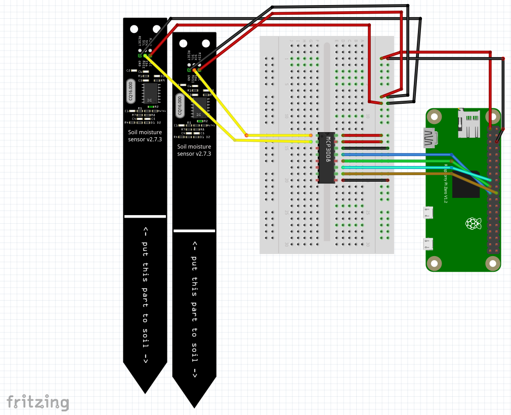
Pull out 3 corresponding m2m black, red, and yellow wires from your supply. Insert the corresponding colored wires into the sensor wire (e.g. red to red, black to black) so you have a longer reach from the pi to the plant. You can chain these multiple times to get extra length, but I find 1-2 reaches everything. If you loosely braid the wires, it will help prevent tangling once other sensors start coming online. The black cable should be placed into the negative column on the right side of the breadboard and red cable should be placed next to it in the power column on the right side of the breadboard. The yellow wire should be inserted in the top left side of the MCP3008 chip Once wires from the raspberry pi. See the diagram below for full wiring:

The same wiring steps can be completed for up to 8 moisture sensors signals to be processed by the MCP3008.
step 4: Testing the moisture sensor
With the raspberry pi initial setup complete and the initial hard wiring done, you will want to test the sensor. The following script will allow a correctly wired sensor to test in a cup of water:
import RPi.GPIO as GPIO
import spidev
import time

spi = spidev.SpiDev()
spi.open(0,0)
spi.max_speed_hz = 1000000

def readData(channel):
    adc = spi.xfer2([1,(8+channel)<<4,0])
    data = ((adc[1]&3) << 8) + adc[2]
    return data

GPIO.setwarnings(False)
GPIO.setmode(GPIO.BCM)

try:
    while True:
        print(readData(0))
    time.sleep(2)
finally:
    GPIO.cleanup()
Copy the above into a notepad text document or (use an editor like VSCode) and name it something such as ‘moistureTest.py’.
Power on the raspberry pi device and connect to it from the PC using WinSCP. Copy the moistureTest file onto the raspberry pi and then use terminal to run it. Example:
sudo python3 moistureTest.py
This script running in terminal should allow you to dip the moisture sensor tip into a cup of water and see the signal drop. For my system, a dry sensor is around 750 and a sensor in water is around 300. If you are seeing anything around those values (or the values change at all with water applied), it should be working. Hit Ctrl-C when you want to stop the script.
The important part to note in the script above is the readData function. The parameter entered (0-7) will correspond to the moisture sensor pin position next to the MCP3008 chip on the breadboard. You can repeat the above steps to add and test up to 8 sensors with this chip. The more sensor data you collect on different plants, the more interesting information you can pull out.
Next we will add atmospheric sensor data with the BME280.